figure 1
The JSIM Designer
The JSIM Designer a graphical tool for designing and generating JSIM simulation models.
Running the Designer
The designer can be executed directly using the command
java jsim.jmodel.NetFrame. The designer can
also be executed using the jmod.sh command.
figure 1
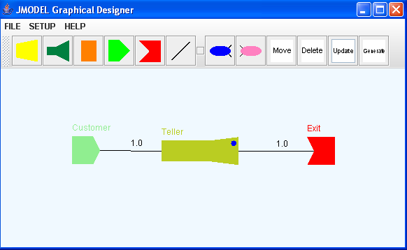
Designing a JSIM Model
JSIM models are represented as a graph where the vertices are
JSIM nodes (these are listed below) and
the edges are JSIM transports. Simulation entities are
generated by JSIM source nodes and travel
along the graph making use of the various nodes in the graphs
until they reach the sink node. Models are
built by clicking on an icon in the toolbar and then clicking
in the canvas area to place the selected node
on the canvas. The graph is created by placing nodes on the
canvas and connecting the nodes with each
other using transports.
JSIM Nodes
Each of the JSIM node types are described below:
![]() Source nodes generate simulation entities based on the source's mean
inter-arrival time and
Source nodes generate simulation entities based on the source's mean
inter-arrival time and
distribution parameters.
![]() Server nodes process simulation entities based on the server's mean
service time and
Server nodes process simulation entities based on the server's mean
service time and
distribution parameters. Server nodes cannot queue entities; therefore waiting
to be processed
are lost.
![]() Facility nodes process simulation entities based on the facility's mean
service time and
Facility nodes process simulation entities based on the facility's mean
service time and
distribution parameters. Facility nodes have the ability to queue entities that
are waiting to be
processed.
![]() Split nodes clone incoming simulation entities and send the cloned entity
and the original entity
Split nodes clone incoming simulation entities and send the cloned entity
and the original entity
are across different paths in the graph. Each split node is required to have a
matching
join which will join the origin and the cloned entity. Each split node must have
two outgoing
edges.
![]() Join nodes merge cloned entities with matching original entities. Each
join node must have two
Join nodes merge cloned entities with matching original entities. Each
join node must have two
incoming edges.
![]() Sink nodes terminate a graph and consume simulation entities.
Sink nodes terminate a graph and consume simulation entities.
![]() Transports are used to connect two nodes. To place a transport in the
model click on the
Transports are used to connect two nodes. To place a transport in the
model click on the
transport icon then click on the two nodes on the canvas that are to be
connected.
Toolbar Edit Icons
Each of the edit icons on the toolbar are described below:
![]() The move icon is used to reposition nodes on the canvas. To move a
node click on the move
The move icon is used to reposition nodes on the canvas. To move a
node click on the move
icon, click on the node to be moved then click on the place on the canvas to
which the node is
to be moved.
![]() The delete icon is used to delete nodes from the canvas. To delete
a node click on the delete
The delete icon is used to delete nodes from the canvas. To delete
a node click on the delete
icon then click on the node to be deleted.
![]() The generate icon is used to generate the model that is displayed
on the canvas. To generate
The generate icon is used to generate the model that is displayed
on the canvas. To generate
the model click on the generate icon then click on the canvas. The generated
model is made
up of java source files. The source files will automatically be placed in the
directory from which
the designer was started. The generated source file that contains the startup
code for the model
will be named JModel.java by default. The default name can be overridden
by using the
"Save As" menu option on the "File" menu to save the model under a different
name prior to
generating the model. The generated source files must be compiled before the
model can be
executed.
![]() The update icon is used to update node parameters and transports. To update a
node's
The update icon is used to update node parameters and transports. To update a
node's
parameters click on
the update icon then click on the node whose parameters are to be
updated. This
will cause the
parameters window shown below to be displayed.
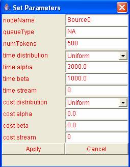
The parameters fields are described below:
nodeName: The name placed in this field will appear above
the parameter when it is displayed on the canvas.queueType: This parameter is used only with facility nodes.The
value will default to "LinkedList" for facility nodes and
"NA" for all other node types. A FIFO queue
implemented using a linked list is the only queue
supported by facility nodes at present.numTokens: This parameter represents different things in different
nodes. It uses with various node types is listed below:Node Type Meaning of numTokens
Source Number of simulation entities
generated by the sourceServer Number of service units in the
in the serverFacility Number of service units in the
facilitytime distribution: This parameter represents the distribution used
in the generation of the inter-arrival time of
source nodes and the service time of server and
facility nodes. The dropdown list associated with
this parameter can be used to select a
distribution.
time alpha: The alpha parameter of the time distribution.time beta: The beta parameter of the time distribution.
time stream: The random number stream of the time
distribution.cost distribution: This parameter represents the distribution used
in the generation of the service cost of server
and facility nodes. The dropdown list
associated with this parameter can be used to
select a distribution.cost alpha: The alpha parameter of the cost distribution.
cost beta: The beta parameter of the cost distribution.
cost stream: The random number stream of the cost
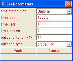
distribution.As mentioned earlier the update icon can also be used to set parameters for a
transport. To set the parameters for a transport click on the update icon and
then click on the transport. This will cause the the window shown below to be
displayed.
The parameters fields are described below:
time distribution: This parameter represents the distribution used
in the generation of the move time of a transport
The dropdown list associated with this
parameter can be used to select a distribution.time alpha: The alpha parameter of the move time
distribution.time beta: The beta parameter of the move time
distribution.time stream: The random number stream of the move time
distribution.out cond: This field works in conjunction with the out
cond type field to determine whether or not a
simulation object should travel across the
transport. The list below describes the
interaction between the two fields:out cond. type Meaning of the out cond Field
probability The value in the out cond field
represents the probability that a
simulation entity will travel across
this transport. The value should
be a number between 0 and 1.0.class id The out cond field should contain
a condition that will determine
whether or not a simulation entity
will travel across the transport.
The condition will be used to
allow only entities with specified
class id values to use the
transport.cost The out cond field should contain
a condition that will determine
whether or not a simulation entity
will travel across the transport.
The condition will be used to
test allow only entities with the
specified cost values to use
the transport.out cond. type: This field works in conjunction with the out
cond field as described above. The out cond
type can be selected using the drop down list
associated with the field.
Running a JSIM Model
A JSIM model can be executed by running the model class file. Model class files have the name JModel by default but can be renamed using the "Save As" option on the file menu. The command "java JModel" will execute a model named JModel.
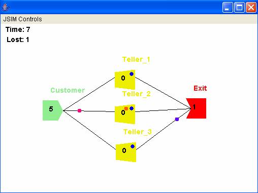
figure 2
JSIM Controls
The JSIM controls menu can be accessed by clicking "JSIM
Controls" on the menu bar. The menu options
are described below:
Start Simulation: Selecting this option will cause the simulation to begin execution.
Start Animation: Selecting this option will cause the animation of the simulation to begin.
Stop Animation: Selecting this option will cause the animation to stop.
Speed Up: Selecting this option will cause the animation to speed up.
Slow Down: Selecting this option will cause the animation to slow down.
Show
Statistics: Selecting this option will cause
the simulation statistics to be displayed. The
statistics window is shown below.
Toggle Trace:
This option turns the debug log on and off. Debugging information is logged
by default. Selecting this option initially will stop the information from being
logged.